In the field of high-speed and high-precision electronic manufacturing, electronic needle test adapters serve as the gatekeepers ensuring the quality of PCBs, chips, and modules. As component pin spacing becomes increasingly smaller and testing complexity escalates, the demands for precision and reliability in testing have reached unprecedented heights. In this revolution of precision measurement, micro stepper motors play an indispensable role as the “precise muscles”. This article will delve into how this tiny power core works precisely in electronic needle test adapters, driving modern electronic testing into a new era.
一. Introduction: When the testing accuracy is required to be at the micron level
Traditional testing methods have become inadequate for the testing needs of today’s micro-pitch BGA, QFP, and CSP packages. The core task of an electronic needle test adapter is to drive dozens or even thousands of test probes to establish reliable physical and electrical connections with the test points on the unit under test. Any minor misalignment, uneven pressure, or unstable contact can lead to test failure, misjudgment, or even product damage. Micro stepper motors, with their unique digital control and high-precision characteristics, have become an ideal solution to address these challenges.
一. Core working mechanism of micro stepper motor in adapter

The operation of the micro stepper motor in the electronic needle test adapter is not a simple rotation, but a series of precise and controlled coordinated movements. Its workflow can be broken down into the following core steps:
1. Precise alignment and initial positioning
Workflow:
Receiving instructions: The host computer (test host) sends the coordinate data of the component to be tested to the motion control card, which converts it into a series of pulse signals.
Pulse conversion motion: These pulse signals are sent to the driver of the micro stepper motor. Each pulse signal drives the motor shaft to rotate a fixed angle – a “step angle”. Through advanced microstepping drive technology, a complete step angle can be subdivided into 256 or even more microsteps, thus achieving micrometer-level or even submicrometer-level displacement control.
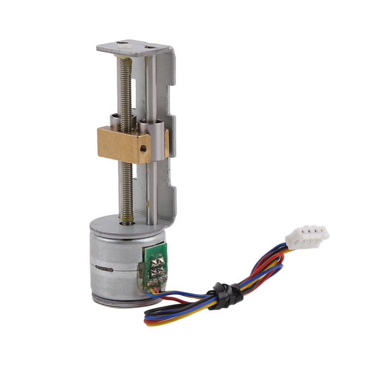
Execution positioning: The motor, through transmission mechanisms such as precision lead screws or timing belts, drives the carriage loaded with test probes to move on the X-axis and Y-axis planes. The system precisely moves the probe array to the position directly above the point to be tested by sending a specific number of pulses.
2. Controlled compression and pressure management
Workflow:
Z-axis approximation: After completing the plane positioning, the micro stepper motor responsible for Z-axis movement starts to work. It receives instructions and drives the entire test head or a single probe module to move vertically downward along the Z-axis.
Precise travel control: The motor smoothly presses down in micro-steps, precisely controlling the travel distance of the press. This is crucial, as a too short travel distance can lead to poor contact, while a too long travel distance may overcompress the probe spring, resulting in excessive pressure and damage to the solder pad.
Maintaining Torque to Sustain Pressure: When the probe reaches the preset contact depth with the test point, the micro stepper motor stops rotating. At this point, the motor, with its inherent high holding torque, will be firmly locked in place, maintaining a constant and reliable downforce without the need for continuous power supply. This ensures the stability of the electrical connection throughout the entire testing cycle. Especially for high-frequency signal testing, stable mechanical contact is the foundation of signal integrity.
3. Multi-point scanning and complex path testing
Workflow:
For complex PCBs that require testing of components in multiple different areas or at different heights, adapters integrate multiple micro stepper motors to form a multi-axis motion system.
The system coordinates the movement of various motors according to a pre-programmed test sequence. For example, it first tests Area A, then the X-Y motors move in coordination to move the probe array to Area B, and the Z-axis motor presses down again for testing. This “flight test” mode greatly improves testing efficiency.
Throughout the entire process, the motor’s precise position memory capability ensures the repeatability of positioning accuracy for each movement, eliminating cumulative errors
一. Why choose micro stepper motors? – Advantages behind the working mechanism
The aforementioned precise working mechanism stems from the technical characteristics of the micro stepper motor itself:
Digitalization and Pulse Synchronization: The position of the motor is strictly synchronized with the number of input pulses, enabling seamless integration with computers and PLCs for full digital control. It is an ideal choice for automated testing
No cumulative error: Under non-overload conditions, the step error of the stepper motor does not accumulate gradually. The accuracy of each movement depends solely on the inherent performance of the motor and driver, ensuring reliability for long-term testing.
Compact structure and high torque density: The miniature design allows it to be easily embedded within compact test fixtures, while providing sufficient torque to drive the probe array, achieving a perfect balance between performance and size.
一. Addressing Challenges: Technologies for Optimizing Work Efficiency
Despite its prominent advantages, in practical applications, micro stepper motors also face challenges such as resonance, vibration, and potential step loss. To ensure its flawless operation in electronic needle test adapters, the industry has adopted the following optimization techniques:
In-depth application of micro-stepping drive technology: Through micro-stepping, not only is the resolution improved, but more importantly, the motor’s movement is smoothed, significantly reducing vibration and noise during low-speed creeping, making the probe’s contact more compliant
Introduction of closed-loop control system: In some ultra-high-demand applications, encoders are added to micro stepper motors to form a closed-loop control system. The system monitors the actual position of the motor in real time, and once out-of-step (due to excessive resistance or other reasons) is detected, it will immediately correct it, combining the reliability of open-loop control with the safety guarantee of a closed-loop system.
一. Conclusion
In summary, the operation of micro stepper motors in electronic needle test adapters serves as a perfect example of converting digital instructions into precise movements in the physical world. By performing a series of precisely controllable actions, including receiving pulses, making micro-step movements, and maintaining position, it undertakes the important tasks of precise alignment, controllable pressing, and complex scanning. It is not only a key executing component for achieving test automation but also a core engine for enhancing test accuracy, reliability, and efficiency. As electronic components continue to evolve towards miniaturization and high density, the technology of micro stepper motors, especially its micro-stepping and closed-loop control technology, will continue to propel electronic testing technology to new heights.
Post time: Nov-26-2025