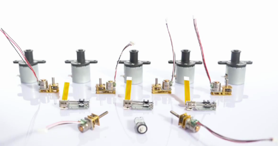
In automation equipment, precision instruments, robots, and even daily 3D printers and smart home devices, micro stepper motors play an indispensable role due to their precise positioning, simple control, and high cost-effectiveness. However, facing the dazzling array of products on the market, how to choose the most suitable micro stepper motor for your application? A deep understanding of its key parameters is the first step towards successful selection. This article will provide a detailed analysis of these core indicators to help you make informed decisions.
1. Step Angle
Definition: The theoretical angle of rotation of a stepper motor upon receiving a pulse signal is the most fundamental accuracy indicator of a stepper motor.
Common values: The common step angles for standard two-phase hybrid micro stepper motors are 1.8 ° (200 steps per revolution) and 0.9 ° (400 steps per revolution). More precise motors can achieve smaller angles (such as 0.45 °).
Resolution: The smaller the step angle, the smaller the angle of the motor’s single step movement, and the higher the theoretical position resolution that can be achieved.
Stable operation: At the same speed, a smaller step angle usually means smoother operation (especially under micro step drive).
Selection points: Choose according to the minimum required movement distance or positioning accuracy requirements of the application. For high-precision applications such as optical equipment and precision measuring instruments, it is necessary to choose smaller step angles or rely on micro step drive technology.
2. Holding Torque
Definition: The maximum static torque that a motor can generate at rated current and in an energized state (without rotation). The unit is usually N · cm or oz · in.
Importance: This is the core indicator for measuring the power of a motor, determining how much external force the motor can resist without losing step when stationary, and how much load it can drive at the moment of start/stop
Impact: Directly related to the load size and acceleration capability that the motor can drive. Insufficient torque can lead to difficulty starting, loss of step during operation, and even stalling.
Selection points: This is one of the primary parameters to consider when selecting. It is necessary to ensure that the holding torque of the motor is greater than the maximum static torque required by the load, and there is sufficient safety margin (usually recommended to be 20% -50%). Consider friction and acceleration requirements.
3. Phase Current
Definition: The maximum current (usually RMS value) allowed to pass through each phase winding of a motor under rated operating conditions. Unit Ampere (A).
Importance: Directly determines the magnitude of torque that the motor can generate (torque is approximately proportional to current) and temperature rise.
The relationship with the drive: is crucial! The motor must be equipped with a driver that can provide the rated phase current (or can be adjusted to that value). Insufficient driving current can cause a decrease in motor output torque; Excessive current may burn out the winding or cause overheating.
Selection points: Clearly specify the required torque for the application, select the appropriate current specification motor based on the torque/current curve of the motor, and strictly match the current output capability of the driver.
4. Winding resistance per phase and winding inductance per phase
Resistance (R):
Definition: The DC resistance of each phase winding. The unit is ohms (Ω).
Impact: Affects the power supply voltage demand of the driver (according to Ohm’s law V=I * R) and copper loss (heat generation, power loss=I ² * R). The larger the resistance, the higher the required voltage at the same current, and the greater the heat generation.
Inductance (L):
Definition: The inductance of each phase winding. Unit millihenries (mH).
Impact: is crucial for high-speed performance. Inductance can hinder rapid changes in current. The larger the inductance, the slower the current rises/falls, limiting the motor’s ability to reach rated current at high speeds, resulting in a sharp decrease in torque at high speeds (torque decay).
Selection points:
Low resistance and low inductance motors typically have better high-speed performance, but may require higher driving currents or more complex driving technologies.
High speed applications (such as high-speed dispensing and scanning equipment) should prioritize low inductance motors.
The driver needs to be able to provide a sufficiently high voltage (usually several times the voltage of ‘I R’) to overcome inductance and ensure that current can quickly establish at high speeds.
5. Temperature Rise and Insulation Class
Temperature rise:
Definition: The difference between the winding temperature and the ambient temperature of a motor after reaching thermal equilibrium at rated current and specific operating conditions. Unit ℃.
Importance: Excessive temperature rise can accelerate insulation aging, reduce magnetic performance, shorten motor life, and even cause malfunctions.
Insulation level:
Definition: The level standard for the heat resistance of motor winding insulation materials (such as B-level 130 ° C, F-level 155 ° C, H-level 180 ° C).
Importance: determines the maximum allowable operating temperature of the motor (ambient temperature+temperature rise+hot spot margin ≤ insulation level temperature).
Selection points:
Understand the environmental temperature of the application.
Evaluate the duty cycle of the application (continuous or intermittent operation).
Choose motors with sufficiently high insulation levels to ensure that the winding temperature does not exceed the upper limit of the insulation level under expected working conditions and temperature rise. Good heat dissipation design (such as installing heat sinks and forced air cooling) can effectively reduce temperature rise.
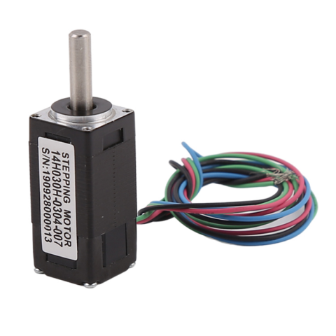
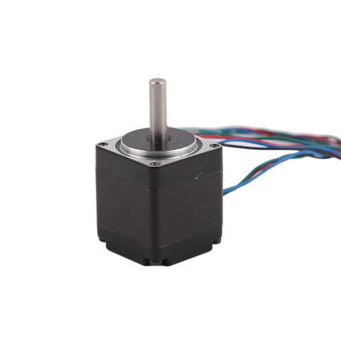
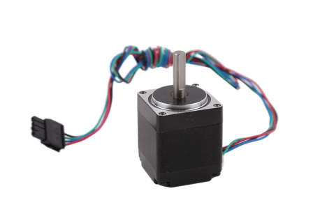
6. Motor size and installation method
Size: mainly refers to the flange size (such as NEMA standards such as NEMA 6,NEMA 8, NEMA 11, NEMA 14, NEMA 17, or metric sizes such as 14mm,20mm, 28mm, 35mm, 42mm) and body length of the motor. The size directly affects the output torque (usually the larger the size and the longer the body, the greater the torque).
NEMA6(14mm):
NEMA8(20mm):
NEMA11(28mm):
NEMA14(35mm):
NEMA17(42mm):
Installation methods: Common methods include front flange installation (with threaded holes), rear cover installation, clamp installation, etc. It needs to be matched with the equipment structure.
Shaft diameter and shaft length: The diameter and extension length of the output shaft need to be adapted to the coupling or load.
Selection criteria: Choose the minimum size allowed by space constraints while meeting torque and performance requirements. Confirm the compatibility of installation hole position, shaft size, and load end.
7. Rotor Inertia
Definition: The moment of inertia of the motor rotor itself. The unit is g · cm ².
Impact: Affects the acceleration and deceleration response speed of the motor. The larger the inertia of the rotor, the longer the start stop time required, and the higher the requirement for the acceleration capability of the drive.
Selection points: For applications that require frequent start stop and rapid acceleration/deceleration (such as high-speed pick and place robots, laser cutting positioning), it is recommended to choose motors with small rotor inertia or ensure that the total load inertia (load inertia+rotor inertia) is within the recommended matching range of the driver (usually recommended load inertia ≤ 5-10 times the rotor inertia, high-performance drives can be relaxed).
8. Accuracy level
Definition: It mainly refers to the step angle accuracy (the deviation between the actual step angle and the theoretical value) and the cumulative positioning error. Usually expressed as a percentage (such as ± 5%) or angle (such as ± 0.09 °).
Impact: Directly affects the absolute positioning accuracy under open-loop control. Out of step (due to insufficient torque or high-speed stepping) will introduce greater errors.
Key selection points: Standard motor accuracy can usually meet most general requirements. For applications that require extremely high positioning accuracy (such as semiconductor manufacturing equipment), high-precision motors (such as within ± 3%) should be selected and may require closed-loop control or high-resolution encoders.
Comprehensive consideration, precise matching
The selection of micro stepper motors is not just based on a single parameter, but needs to be comprehensively considered according to your specific application scenario (load characteristics, motion curve, accuracy requirements, speed range, space limitations, environmental conditions, cost budget).
1. Clarify core requirements: Load torque and speed are the starting points.
2. Matching the driver power supply: The phase current, resistance, and inductance parameters must be compatible with the driver, with particular attention to high-speed performance requirements.
3. Pay attention to thermal management: ensure that the temperature rise is within the allowable range of insulation level.
4. Consider physical limitations: The size, installation method, and shaft specifications need to be adapted to the mechanical structure.
5. Evaluate dynamic performance: Frequent acceleration and deceleration applications require attention to rotor inertia.
6. Accuracy verification: Confirm whether the step angle accuracy meets the requirements of open-loop positioning.
By delving into these key parameters, you can clear the fog and accurately identify the most suitable micro stepper motor for the project, laying a solid foundation for the stable, efficient, and precise operation of the equipment. If you are looking for the best motor solution for a specific application, feel free to consult our technical team for personalized selection recommendations based on your detailed needs! We provide a full range of high-performance micro stepper motors and matching drivers to meet diverse needs from general equipment to cutting-edge instruments.
Post time: Aug-18-2025