Part winding between wire center tap, or between two wire(when without center tap).
Rotated angle of the no-load motor, while two neighboring phase are excited
The rate of the stepper motor’s continuous stepping movement.
The maximum torque that the shaft can withstand without continuous rotation, while lead wires are disconnected.
The maximum static torque that the shaft of a stepper motor excited with rated current can withstand without continuous rotation.
The maximum pulse rates that the excited stepper motor with a certain load can startup and no desynchronizing.
The maximum pulse rates that the excited stepper motor driving a certain load can reach to and keep no desynchronizing.
The maximum torque that the excited stepper motor can startup on a certain pulse rate and keep no desynchronizing.
The maximum torque that the a stepper motor driven on prescriptive conditions and a certain pulse rate can withstand and keep no desynchronizing.
The pulse rate range that the stepper motor with prescriptive load can startup, stop or reveres, and keep no desynchronizing.
The peak voltage measured across a phase, when carrying the motor’s shaft at the constant speed of 1000 RPM.
Difference between the theoretical and actual integrated angles(positions).
Difference between the theoretical and actual one step angle.
Difference between the stop positions for CW and CCW.
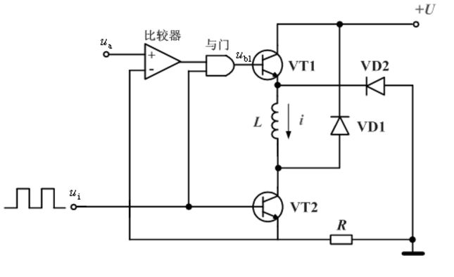
Chopper constant current drive circuit is a kind of drive mode with better performance and more use at present. The basic idea is that the current rating of the conductive phase winding is maintained regardless of whether the stepper motor is in a locked state or running in low or high frequency. BellowFigure is the schematic diagram of chopper constant current drive circuit, in which only one phase drive circuit is shown, and another phaseare the same. The on-off of the phase winding is controlled jointly by the switching tube VT1 and VT2. The emitter of VT2 is connected with a sampling resistance R, and the pressure drop on the resistance is proportional to the current I of the phase winding.
When the control pulse UI is at high voltage, both VT1 and VT2 switch tubes are switched on, and the dc power supply supplies the winding. Due to the influence of inductance of the winding, the voltage on the sampling resistance R increases gradually. When the value of the given voltage Ua is exceeded, the comparator outputs low level, so that the gate also outputs low level. VT1 is cut off and the dc power supply is cut off. When the voltage on the sampling resistance R is less than the given voltage Ua, the comparator output high level, and the gate also output high level, VT1 is switched on again, and the dc power supply starts to supply power to the winding again. Over and over again, the current in the phase winding is stabilized at a value determined by the given voltage Ua.
When using a constant voltage drive, the power supply voltage matches the rated voltage of the motor and remains constant. Constant voltage drives are simpler and cheaper than constant current drives, which regulate the supply voltage to ensure a fixed constant current is provided to the motor. For constant voltage drive, the resistance of the drive circuit will limit the maximum current, and the inductance of the motor will limit the speed at which the current rises. At low speeds, resistance is the limiting factor for current (and torque) generation. The motor has good torque and positioning control and runs smoothly. However, as the motor speed increases, the inductance and current rise time start to prevent the current from reaching its target value. Moreover, as the motor speed increases, the back EMF also increases, which means that more power supply voltage is only used to overcome the back EMF voltage. Therefore, the main disadvantage of constant voltage drive is the rapid drop in torque produced at a relatively low speed of the stepper motor.
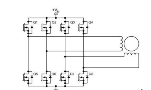
The driving circuit of a bipolar stepper motor is shown in Figure 2. It uses eight transistors to drive two sets of phases. The bipolar drive circuit can drive four-wire or six-wire stepper motors at the same time. Although the four-wire motor can only use the bipolar drive circuit, it can greatly reduce the cost of mass production applications. The number of transistors in a bipolar stepping motor drive circuit is twice that of a unipolar drive circuit. The four lower transistors are usually directly driven by a microcontroller, and the upper transistor requires a higher cost upper drive circuit. The transistor of the bipolar drive circuit only needs to bear the motor voltage, so it does not need a clamp circuit like the unipolar drive circuit.
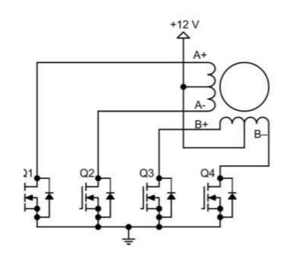
Unipolar and bipolar are the most commonly used drive circuits that the stepping motors are used. The single-polar driving circuit uses four transistors to drive the two sets of phases of the stepping motor, and the motor stator winding structure includes two sets of coils with intermediate taps (the intermediate tap of the AC coil O, BD coil) The intermediate tap is m), and the entire motor has a total of six lines with an external connection. The AC side cannot energize (BD ending), otherwise the magnetic flux generated by the two coils on the magnetic pole cancels each other, only the copper consumption of the coil is generated. Because it is actually only two phases (AC windings are one phase, the BD winding is one phase), the accurate statement should be two-phase six-wire (of course, now there are now five lines, it is connected to the two public lines) Stepping motor.
One-phase, the power-on winding only one phase, sequentially switching the phase current generating the rotational step angle (different electric machines, 18 degrees 15 7.5 5, mixed motor 1.8 degrees and 0.9 degrees, the following 1.8 degrees are referenced to this excitation method, and the response of the rotation angle when each pulse arrives is vibrated. If the frequency is too high, it is easy to generate an out-of-date.
Two-phase excitation: two-phase simultaneous circulation current, also uses a method of switching phase currents in turn, the second-phase intensity step angle is 1.8 degrees, the total current of the two sects is 2 times, and the highest starting frequency increases, can be obtained High speed, additional, excessive performance.
1-2 Excitation: This is a method of alternately performing a phase-in excitation, two-phase excitation, starting current, each two always switches, so the step angle is 0.9 degrees, the excitation current is large, and the over-performance is good. The maximum starting frequency is also high. Commonly known as half-way excitation drive
Post time: Jul-06-2023